


The M7 was Drummond’s first design for the LSWR.
It is basically the Loco part of the T9 with smaller driving wheels and a shorter firebox, and obviously reversed.
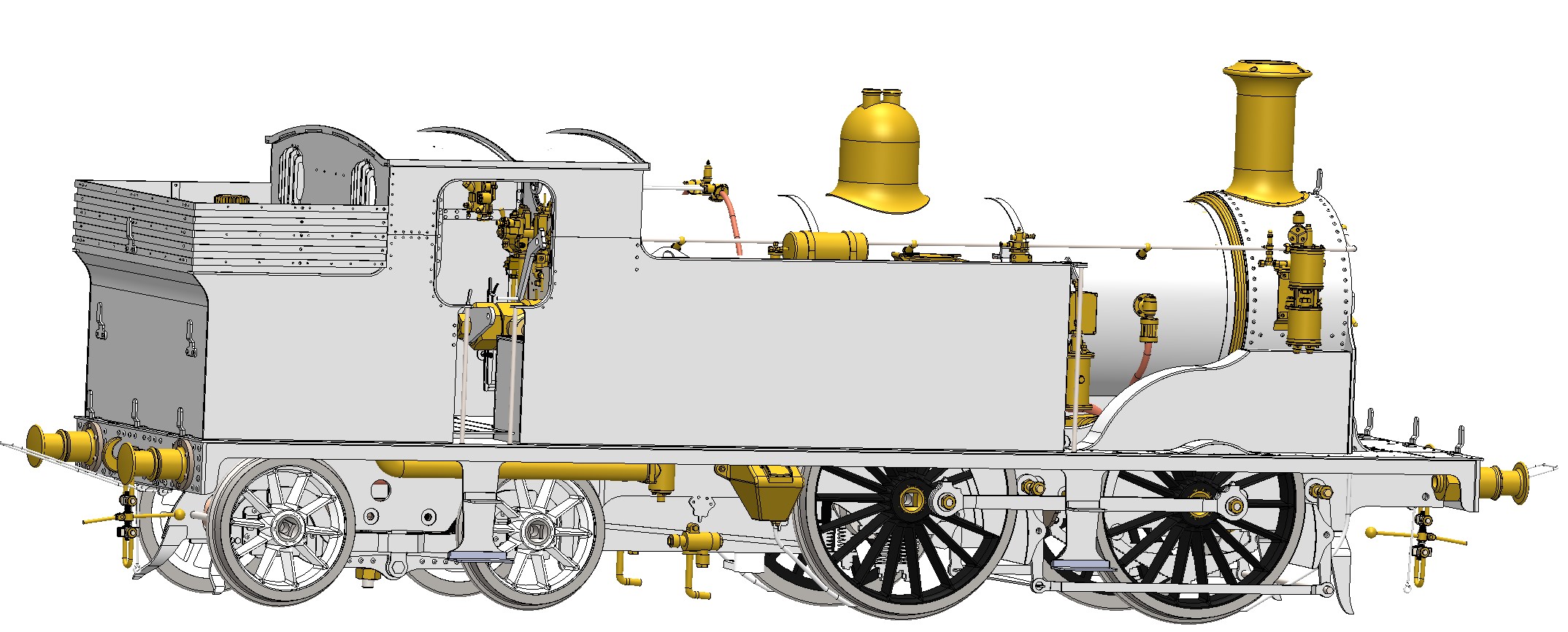
The first 2 images show the early position of my mechanical design for the M7.
09/2020 – the design has changed slightly – mostly added detail, rearrangement of some parts and a smaller LiPo cell – the one shown turned out to be too big when the bodywork was fitted.
The final two drawings show the current position of the overall design. Pretty near complete – just a few bits of dummy pipework missing.
NOTE – the castings for the Southern pull-push fittings shown on the drawing will be available separately – no prices yet.
NOTE to all operators of long frame M7 models (including the Bowande ones) – all BR M7s with long frame should have the fittings (except 3 locos – 30, 127 & 479). All except another 5 (48, 52, 328, 379 & 480) were fitted 1930-1, those remaining 5 in 1937-8.
Expect the loco to cost slightly more than the Adams Radial Tank – fewer wheels, but more castings.
Note the clear cab – no visible regulator and full backhead detail. Only needs a driver figure & fireman to complete the effect. They would also help to hide the poker burner. It would be good to have the driver leaning out of the cab with a rotating head linked to the reverser so that he looks in the direction of travel – no prizes for the first to do it!
Like all of my current models this is entirely made of nickel silver with lost-wax brass castings made from 3D printed masters, copper boiler, thick walled brass gas tank and, in this case a mix of plastic centred & cast-iron wheels. The boiler uses a single flue with a poker burner that is remotely adjustable for idling.
The model is radio controlled only – no manual option – it would have involved too many compromises.
See here for more details of the R/C system. It provides controls for the regulator, reverser, idling the burner and uncoupling. It also provides feedback on speed, boiler pressure, water level and battery voltage with warnings when pressure goes too high, or voltage or water level too low. The system is fully integrated at no extra cost.
References
Wikipedia https://en.wikipedia.org/wiki/LSWR_M7_class
Maskelyne J. M. Locomotives I have known MAP Out of Print
Roche F. J. Historic Loco Drawings in 4mm scale Ian Allan Out of Print
Beattie I. Drawn & Described Peco ?
Curl B. The LSWR at Nine Elms Kestrel
Burtt F. LSWR Locomotives Ian Allan Out of Print
Russell J. H. A Pictorial Record of Southern Locomotives OPC Out of Print
Herring P. Handbook of Classic British Steam Locomotives Island Books ?
Harris M. Locos Illustrated 73 – South Western 0-4-4Ts Ian Allan Out of Print
Swift P. The book of the M7 0-4-4Ts Irwell Press
File From Nine Elms to Waterloo – the story of Drummond Loco Society
M7 class no. 30053
NRM Works GA drawings
Preserved loco (245) at the NRM
NRM page for this no longer appears to be available
Preserved loco (30053) at the Swanage Railway
http://www.swanagerailway.co.uk/stock/detail/lswr-0-4-4t-class-m7-no-30053 follow links on pages for more
Downloads
Click here to download the Southern valvegear instructions
Note the exploded drawing instructions are not yet ready
Click here to download the punching rivets PDF from Google Drive and other common PDF documents
See the assembly instructions PDF for assembly photos